When we are touched by something it's as if we're being brushed by an angel's wings.
—Rita Dove
Capacitive Sensing is ubiquitous now, from your smartphone screen, or your Apple iPod, to the "buttons" on your new TV remote control. Today we'll be talking about how capacitive sensing works and how you can use it on your next project.
Capacitive Sensing is a technology that uses the human body capacitance as a sensor input to a control interface. If you have used almost any recent smartphone touch screen or a non-mechanical button, then you have likely used a capacitive sensor of some kind. There are many different applications for capacitive sensors, such as distance or proximity measurement, material thickness measurement, fluid level measurement, gyroscopic position, and acceleration measurement. Often the trackpad on your laptop is implemented an X/Y capacitance measurement device.
A Capacitor is formed whenever two conductive surfaces are separated by an insulating layer, which is known as the dielectric layer. Capacitance is measured in Farads. There are many different capacitive sensing algorithms, and the sensors themselves can be constructed from many different materials, such as aluminum, silver, gold, copper, Indium Tin Oxide (ITO), and various printed (conductive) inks. Typically copper capacitive sensors can be implemented using standard FR4 (fiberglass) printed circuit board material itself as the dielectric layer. Touch screen capacitive sensors typically utilize Indium Tin Oxide (ITO) materials because it can be up to ninety percent (90%) transparent, allowing you to see the screen underneath without too much light loss. All capacitive sensing systems work by measuring a change in capacitance as a human interacts with the sensor, and they differ in the method, or algorithm used to measure that capacitance.
Surface Capacitance
Surface capacitance measurement (sometimes referred to as "active" capacitance measurement) is performed by the application of a small voltage to the sensor, which creates a uniform electrostatic field. When a human comes into contact with the sensor, (and hence the electrostatic field) a capacitor is formed dynamically. The capacitative sensor controller measures the change in capacitance to determine the proximity of the human within the electrostatic field.
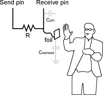
The Arduino Capacitive Sensing Library employs Surface Capacitive sensing (i.e. active sensing), and this requires two (2) pins per sensor element. The Arduino drives the send pin (TX) to a new value, and then the Arduino counts the time the until the receive pin (RX) reaches that same value. The change in capacitance due the presense of a human/finger varies the time for the receive pin (RX) to reach it's final value. Because this type of capacitive sensor requires two (2) pins per element, most commercial sensor solutions are moving away from the Surface Capacitance types, in favor of Projected Capacitance solutions, which typically require only a single pin per sensor element.
Projected Capacitance (Mutual Capacitance)
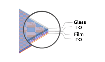
Projected Mutual Capacitance is typically used for touch screen applications, where perpendicual layers of conductive material form an X-Y grid of electrodes (typically composed of Indium Tin Oxide material). The capacitance is measured (usually by scanning the rows and columns over time) to locate one (or more) fingers within the X-Y grid space.
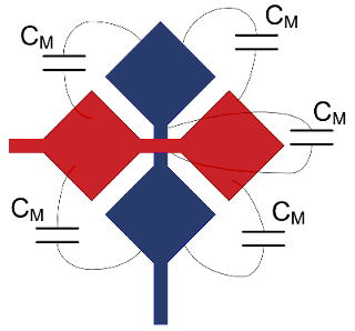
Most of the so-called "multi-touch" systems that allow multiple fingers to be detected are using Projected Mutual Capacitance. We'll be covering this in more detail when we get to Graphic LCD display systems and touch screen overlays. Today we are concentrating on the types of capacitive sensors that can be implemented on your printed circuit boards.
Projected Capacitance (Self Capacitance)
In Projected Self Capacitance, the sensor forms an intrinsic parasitic capacitance (Ci) by coupling with the surrounding ground pattern on the printed circuit board. When a human finger is in close proximity to the sensor pad, it alters the electric field to add an additional capacitance (Cf) to the sensor, which can be measured by the capacitative sensor controller. Once a pre-determined increase in capacitance is measured, the sensor is considered activated. These are also sometimes refered to as "passive capacitance sensors".
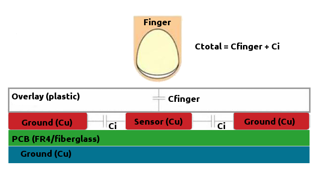
The sensors are continuously scanned, and when the baseline values are exceeded by a pre-determined threshold, the sensor is considered to be activated (ie. the button is pressed).
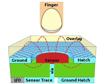
Today we will be concentrating on Projected Self Capacitance (i.e. Passive) solutions for implementing buttons, sliders, dials, proximity, and other sensor patterns using only shapes of copper on your circuit boards. Basically, we are going to show you how to add control surfaces to your projects with almost no additional cost, and greatly increased reliability compared to mechanical buttons, potentiometers, or rotary encoders.
Capacitive Sensing Algorithms
There are many different algorithms for measuring capacitance :
- ADC : where a current source generates a voltage charging ramp on a capacitor that can be sampled using an Analog to Digital Converter (ADC)
- TX/RX : were a tranmitted (TX) source waveform is coupled using via mutual capacitance and sensed on the receiving (RX) end
- Charge Transfer : where the capacitive change to a sensor modifies the charge transfer on the sensor when measured against a reference capacitor
- Relaxation Oscillator : where a sensor capacitance is used to modify the frequency of an oscillator
Relaxation Oscillator
In a relaxation oscillator based system the circuit forms a type of oscillator,
where the change in capacitance of the sensor modifies the frequency of the oscillator, according to :

When a relaxation oscillator is employed, it is based upon the behavior of a physical system's return to equilibrium after being disturbed (i.e. the finger entering the electrostatic field is the disturbance).
In most microprocessor based implementations that include a comparator on the input, the relaxation oscillator would look like :

ADC Algorithms
There are several variations of the Analog to Digital Converter (ADC) capacitive measurement algorithms, and those are usually dependent on the type of ADC employed; namely Capacitive Successive Approximation (CSA), Capacitive Sigma Delta Modulator (CSD),and several others. In general, Capacitive Successive Approximation (CSA) work better in the presence of Radio Frequency (RF) interfere, than the Capacitive Sigma Delta Modulator (CSD) implementation.
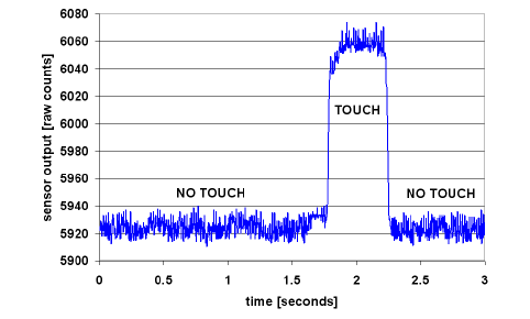
In all cases the raw sensor input is converted to a number of counts, where a threshold of counts is used to determine when a button has been activated/pressed.
An Example Radial Slider Pattern
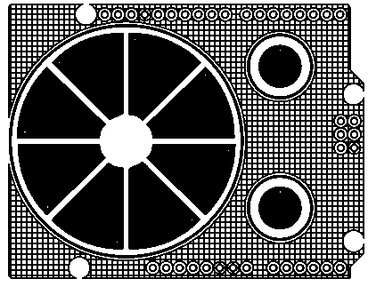
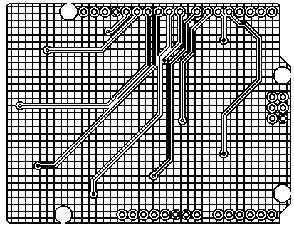
In the next segment, on the PatternAgents Touch Widgets Library for Eagle we will be covering all the open source hardware (OSHW) capacitive touch widgets that we have released on our Github repository. Below is a simple example of a Radial Slider Pattern with two (2) buttons on an Arduino form factor board. Note that this shield board is comprised of just the sensors themselves, and assumes the capacitive sensing controller device is located on another board in the stack-up.
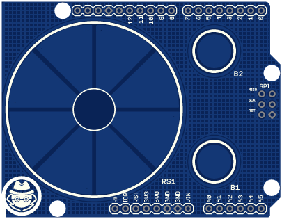
This is an example of what the top and bottom layers of the board would look like, rendered here in black and white so that you can see the ground plane hatch patterns (i.e. the copper pour) more easily.
Thanks for joining us, and come back for the next section where we'll discuss the details of the PatternAgents Touch Widgets Library for Eagle and how you can download and use it to make your own capacitive sensing control surfaces.
