I think that things happen individually first, and then collectively. It's not the other way around.
—Neale Donald Walsch
PatternAgents has been developing open source parts libraries for the Eagle CAD package, and we have now developed a library of Capacitive Touch Widgets to provide a number of different control surfaces for your projects. This How-To will cover instructions for using them in your own projects.
A number of our customers have complained to us how difficult it is to obtain or create good quality Capacitive Touch Widgets in Eagle, so we have spent the past week creating a new library to solve that problem. The PatternAgents Touch Widgets Library makes Capacitive Touch technology available to even the most novice Eagle users.
If you have never used Eagle before, there are several starting tutorials available on the web, such as this one from Jeremy Blum. This How-To assumes that you already have a basic operating knowledge of Eagle, and that can you select a component from a library of parts, and place it in your schematic and layout.
Get the Libraries
The first step is to get the PatternAgents Eagle CAD Libraries from our Github Repo and install them into your Eagle package. You can either copy them into the default library location, which is usually located at "C:\Program Files\EAGLE-6.5.0\lbr", or you can place them anywhere you prefer and add that path to the Eagle Control Panel using "Options -> Directories -> Libraries". Personally I prefer to add the local copy of my Github Repo using the control panel, so that whenever I do a "Github Pull", I get the most recent copies of everything directly from Github.
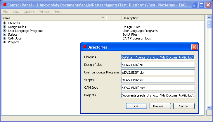
Once you have downloaded, installed, and configured the Touch Widgets Library for Eagle, go ahead and open the library tab to see all the components in the library (Version 1.0 shown) :
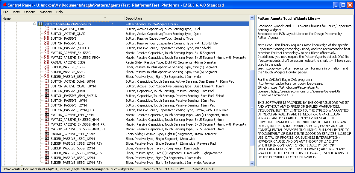
You will see that there are a number of different widgets contained in the library, buttons, buttons with backside LED's, linear sliders, radial sliders, and matrix (X/Y) touch pads of various sizes. The sizes are chosen according to recommended best practices and various manufacturers design rules. We are also working on several new widgets to include in Version 2.0 of this library; so if you have any suggestions or requests, please make sure to leave a comment or tweet to us to let us know. Make sure to right click in the Eagle Control Panel window and select "use" for the PatternAgents-TouchWidgets and PatternAgents-Boards libraries.
In this how-to example, we are going to make a small Arduino Form Factor board that includes several different touch widgets, and will be compatible with a number of different Arduino boards, such as the Pioneer board. We will use the Arduino pins A0 as a select button, and A1-A5 pins for a five (5) button linear slider. This is a simple (arbitrary) example, but will serve to explain all the steps necessary for you to make your own designs.
Create the Schematic File
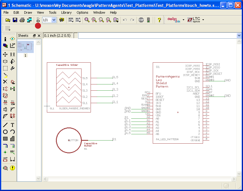
First, we are going to open a new schematic and place the PA_LEO_PATTERN from the PatternAgents-Boards library. This pattern will give you a board outline, connectors, holes, and silkscreen that is compatible with the Arduino Leonardo form factor. This an example of what how our design patterns work, we create reusable design patterns that you can adapt to your own purposes. Next place, BUTTON_PASSIVE_10MM and SLIDER_PASSIVE_5SEGREV from the PatternAgents-TouchWidgets library, and wire them up as show below :
Create the Board File
Next we generate the .brd file from the schematic (click on the icon above the red dot in the picture), and you should have something that looks like this:
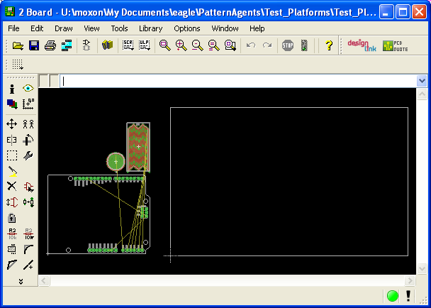
Since the PatternAgents-Boards library includes the board outline we can use the "delete" command to remove the enclosing box, and then move the PA_LEO_PATTERN to the origin in the low left hand corner.
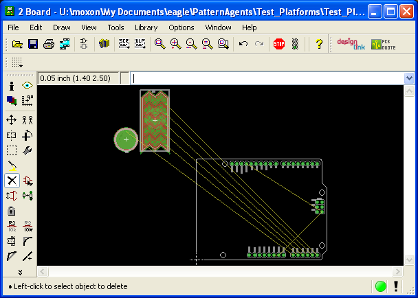
Place the Widgets
Now move the BUTTON_PASSIVE_10MM and SLIDER_PASSIVE_5SEGREV packages onto the PA_LEO_PATTERN and position them near the middle of the board.
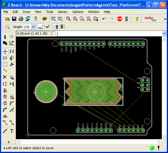
Create the Ground Hatch Polygons
Great, now all we have to do is create the Polygons for the Top and Bottom Copper Ground pours and we are just about finished. Select the Polygon Command and change to the Top layer with a "Hatched" polygon of 10Mil Width, 45Mil spacing, and 12Mil Isolation. (Note that we have our Grid Set to 10Mil spacing for this example) Now click around the edges of the board to create a Polygon on the "Top" layer.
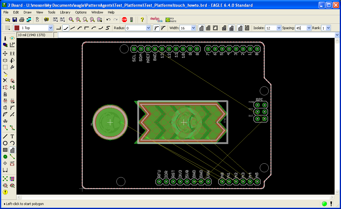
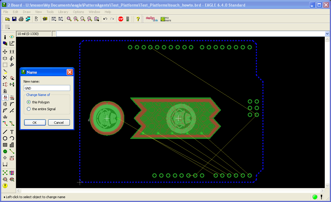
Now we need to name the Polygon to "GND" to make sure the router knows it is to be connected to the "GND" signal in the schematic. Use the "NAME" command and select the Polygon, type in the name "GND" and click OK.
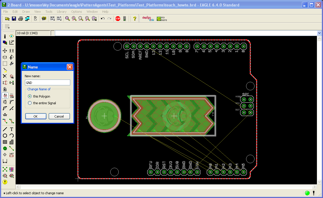
Next we are going to repeat that whole process to make a "Hatched" polygon ground pour on the Bottom layer of of 10Mil Width, 70Mil spacing, and 12Mil Isolation. In this next screen show, I'm going to turn "off" the visibility of the "Top" and "tPlace" layers so you can see the "Bottom" layer more clearly. As before we need to name the Polygon to "GND" to make sure the router knows it is to be connected to the "GND" signal in the schematic. Use the "NAME" command and select the Polygon, type in the name "GND" and click OK.
Run a Design Rule Check (DRC)
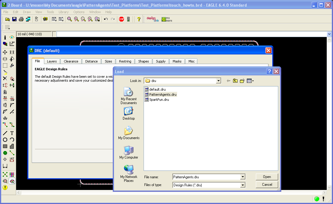
Okay, before we go any further, we should run a Design Rule Check (DRC) to make sure that everthing is good. Make sure to "Load" the PatternAgents.dru file or you will likely get a lot of DRC errors. You should get zero DRC errors when using the PatternAgents.dru file.
Autoroute the Board
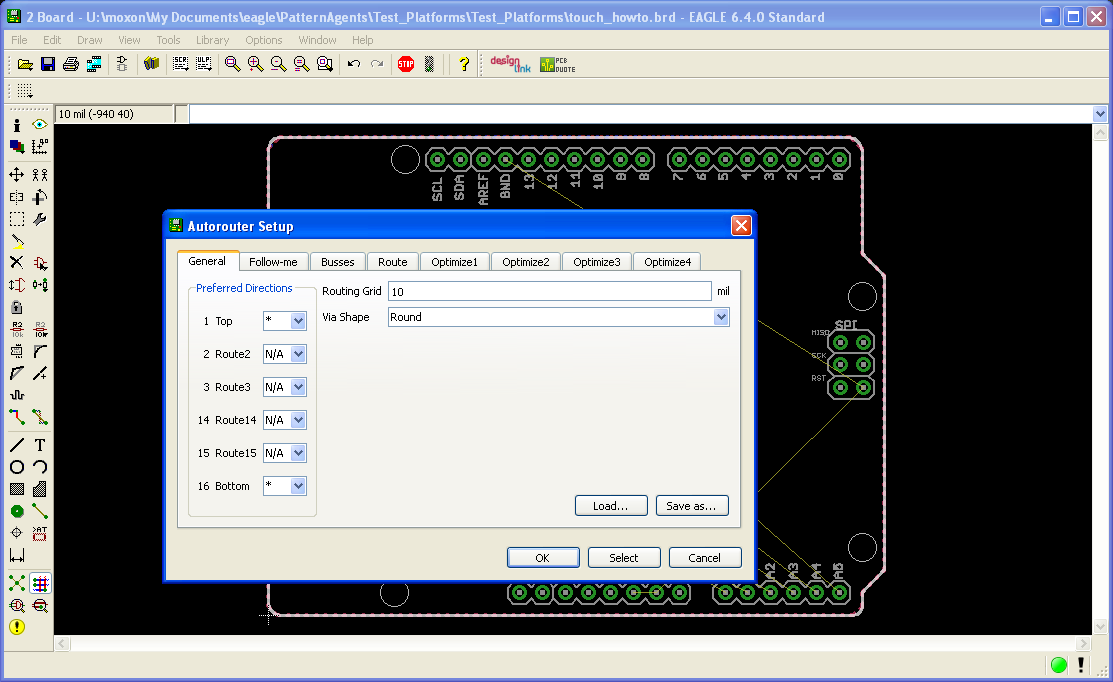
Next we are going to run the autorouter to connect everything up, so set the paramters as shown below, and click "OK".
If you have followed along to this point, then your completed board should look something like this :
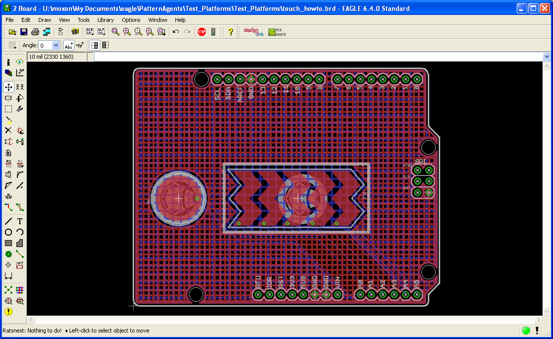
I will turn off the "Top" and "tPlace" (Top Silkscreen) layers so that you can see what the "Bottom" of the board looks like. Note that the Top and Bottom ground hatches are using different spacing.
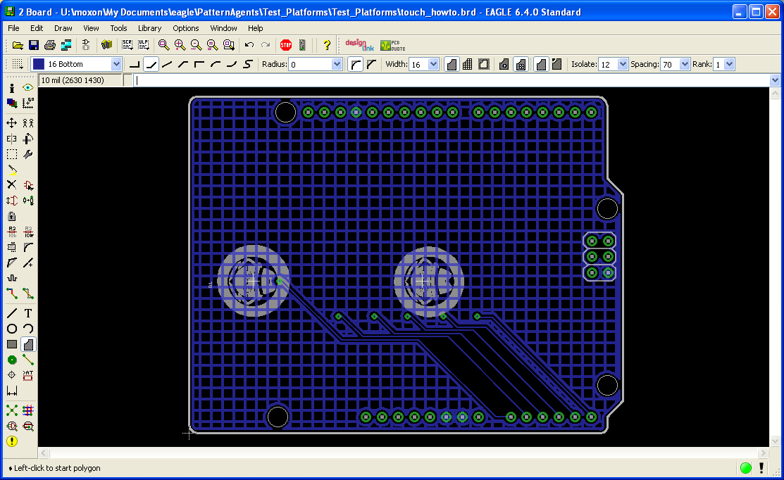
Don't worry if you forgot to set your polygons to "Hatch" or your polygon spacings to 45Mils for the Top and 70Mils for the Bottom, that is easy to fix with the "Change" command (the Wrench icon). Just select "Change->Pour->Hatch" and click on the Polygon edge, and similarly with the "Change->Spacing" command.
Go get your Printed Circuit Boards (PCB's) made...
Viola! You have your very own simple touch control surface example board, using the Arduino form factor. If you load up the PatternAgents.cam file and generate Gerber files, these can be uploaded to OSHPark, and in a week or so you can have your PCB's back.
Now that you have an idea of how to use the Touch Widgets Library for Eagle, in the next posting we'll cover some of the "Best Practices" for using it more effectively.
TouchWidget_HowTo Example Project - Files and Documentation
EagleCad Libraries by PatternAgents, LLC are available and licensed under the Creative Commons License.
License : (Creative Commons 4.0) Creative Commons License
The Touch Widgets How-To Project by PatternAgents, LLC is available and licensed under a
Creative Commons Attribution-ShareAlike 4.0 International License.
